VEKTROX builds thin, high-torque axial-flux drive stacks for OEMs who need real output under real load — not brochure performance.
Our DSSR (dual-stator, single-rotor) architecture with X-coil™ geometry cuts end-turn waste, stabilises thermal behaviour, and packs more copper into every millimetre.
What this means in practice:
- More torque per kg
- Predictable thermal paths
- 800V+ readiness for modern powertrains
- Serviceable, modular housings for fast iteration and lower lifecycle cost
- Carbon-fibre finned case that cools at vehicle speed — no pumps, no drama
This is engineering built for uptime, manufacturability, and transparent spec targets — the way OEMs actually work.
- Dual-stator, single-rotor (DSSR)
- X-coil™ geometry, figure-8 windings
- High-voltage readiness (800V+)
- Finned carbon-fiber housing with passive airflow
- Serviceable stack for rapid iteration and maintenance
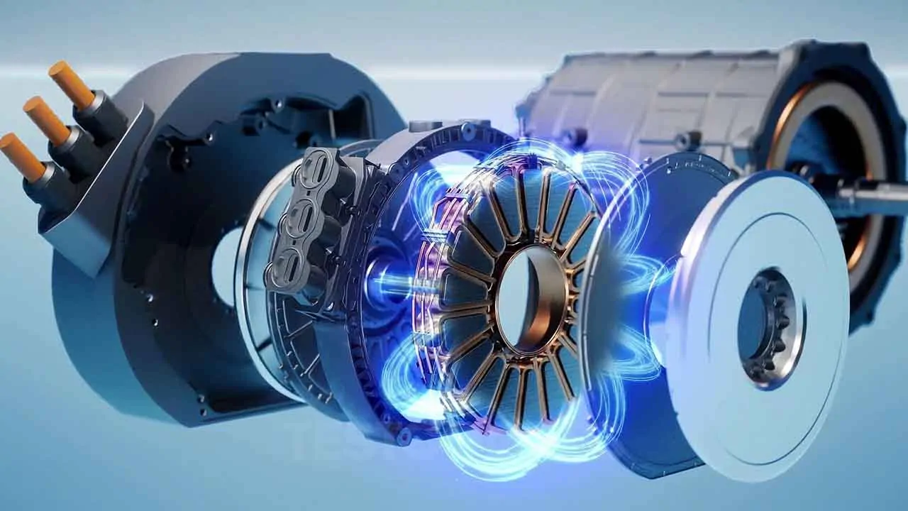
DSSR Overview
Two stators drive a single rotor from both sides.
Both faces load simultaneously — doubling torque density, smoothing thermal behaviour, and removing the bulk of a thick axial rotor profile.
Our DSSR layout shortens flux paths, increases copper utilisation, and keeps the rotor disc simple, stiff, and reliable under load.
The outcome:
More torque per kg, tighter packaging, and predictable thermal performance for high-duty platforms.
Coil Design
Our X-coil™ windings remove the waste and heat penalties of round/triangular coils.
Shorter end-turns = lower resistance and tighter thermal gradients.
Figure-8 (infinity) routing increases packing density and simplifies impregnation
Design advantages:
- Rectangular conductors for maximum fill factor
- Controlled end-turn geometry to cut copper losses
- Clean routing for QC, servicing, and modular assembly
Thermal Path & Cooling
Heat flows directly: copper → stator → case → finned carbon-fiber housing.
No coolant circuits. No pumps. No extra failure nodes.
The carbon-fiber outer case is a structural heatsink: large surface area, high stiffness, and stable continuous output at vehicle airflow speeds.
Thermal benefits:
- Finned carbon-fiber housing for surface area and stability
- Direct copper contact interfaces reduce bottlenecks
- Passive cooling at speed — suitable for most EV/mobility platforms
Efficiency Targets & Testing
We validate on calibrated dyno cycles — not “peak screenshots.”
System target:
≥96% efficiency under representative duty.
Testing includes:
- 800V+ readiness (SiC inverter pairing)
- Loss mapping vs. torque/speed
- Continuous vs peak stability
- Telemetry for thermal and electrical behaviour
Targets are transparent and updated as prototypes mature.
FAQ
What’s the advantage of DSSR over single-stator axial flux?
Both rotor faces are loaded. This doubles torque density, smooths thermal loading, and removes the need for a thick rotor profile.
Why X-coil™ instead of round wire?
Shorter end-turns and higher fill factor reduce copper loss, heat, and winding bulk — giving cleaner thermal behaviour and higher continuous output.
Do I need liquid cooling?
Baseline units use passive finned housing. Liquid cooling is optional for extreme-duty platforms, but most applications won’t require it.
Can the stack be serviced?
Yes — modular assembly allows access during development and production maintenance cycles.
Want the technical deep-dive?
Book a 30-minute session on packaging, thermal strategy, duty-cycle behaviour, and targets.
n the session, we cover:
- DSSR architecture and flux paths
- X-coil™ geometry and copper utilisation
- Thermal interfaces, carbon-fiber housing, and continuous-power behaviour
- Efficiency mapping (96%+ system target)
- 800V+ readiness and inverter pairing
Straight to the point. Real numbers. Real engineering.